How to Use a Router Table: Setup, Safety, and Essential Accessories
What's inside
- What a Router Table Does Better Than a Handheld Router
- Essential Setup Sequence
- Feed Direction: The Rule That Prevents Most Mistakes
- Featherboards and Push Accessories
- Accessory Choices by Workshop Situation
- A Repeatable Workflow for Accurate Cuts
- Safety and Ownership Details That Matter
- Common Mistakes to Avoid
- Related Guides
- What a Router Table Does Better Than a Handheld Router
- Essential Setup Sequence
- Feed Direction: The Rule That Prevents Most Mistakes
- Featherboards and Push Accessories
- Accessory Choices by Workshop Situation
- A Repeatable Workflow for Accurate Cuts
- Safety and Ownership Details That Matter
- Common Mistakes to Avoid
- Related Guides
As an Amazon Associate I earn from qualifying purchases. This post may contain affiliate links at no extra cost to you.
Using a router table safely comes down to four repeatable tasks: install the correct bit, set its height with a gauge, align the fence parallel to the bit, and feed the workpiece from right to left against the bit’s rotation.
As an Amazon Associate we earn from qualifying purchases at no extra cost to you.


Contents
- What a Router Table Does Better Than a Handheld Router
- Essential Setup Sequence
- Feed Direction: The Rule That Prevents Most Mistakes
- Featherboards and Push Accessories
- Accessory Choices by Workshop Situation
- A Repeatable Workflow for Accurate Cuts
- Safety and Ownership Details That Matter
- Common Mistakes to Avoid
- Related Guides
What a Router Table Does Better Than a Handheld Router
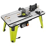
A handheld router is usually the faster choice for edge profiling, template work, and routing large panels. A router table becomes more useful when the workpiece is narrow, the cut must be repeated, or you need both hands available to control the stock. It is especially effective for rabbets, grooves, cope-and-stick joinery, raised panels, pattern work, and long edge profiles.
The table does not make routing automatically safer. An exposed cutter can remove material quickly, and a poorly aligned fence can cause burning, kickback, or an inaccurate joint. Treat the table as a small machine tool: secure the router, control the stock, and make adjustments with the power disconnected.
Essential Setup Sequence
1. Choose and inspect the router bit
Use a sharp, clean bit with a shank that matches the router collet—typically 1/4 inch or 1/2 inch. A 1/2-inch shank is preferable for larger-diameter bits because it generally offers greater stiffness, although the router and collet must be rated for it.
- Inspect carbide edges for chips, cracks, or resin buildup.
- Insert the shank fully, then pull it back approximately 1/16 inch before tightening so it does not bottom out in the collet.
- Never use a bit whose maximum speed is lower than the router’s selected speed.
- Keep the bit’s cutting edges below the collet’s minimum insertion line, if marked.
For large panel-raising or wide profile bits, follow the manufacturer’s speed limit and use the router table’s guard and starting pin where appropriate. Do not improvise with a bit that is too large for the table opening or router.
2. Set the bit height
Disconnect the router from power before making any height adjustment. Start with the bit slightly lower than the intended cut. Raise it in small increments while checking the profile on scrap from the same material and thickness as the project.
A height gauge, setup block, or digital height gauge is more repeatable than measuring from the tabletop with a ruler. For a groove, measure from the table to the relevant cutting edge. For a profile, place a straightedge or sample molding beside the bit and compare the shoulder positions.
When making a joint such as a tongue-and-groove or cope-and-stick profile, save a correctly cut sample. It becomes a reference for resetting the bit after a blade change, cleaning, or future project.
3. Align and set the fence
Close the fence opening around the bit while leaving enough clearance for chips. Both fence faces should be aligned with each other and parallel to the intended feed path. If the outfeed face can be shimmed, use that feature for rabbets or jointing-style cuts; otherwise, keep both faces flush for ordinary edge routing.
Set the fence by measuring from the fence face to the cutting edge at the front and rear of the bit. The two measurements should match for a standard profile. A long steel rule, dial indicator, or straightedge makes alignment more reliable than judging by eye.
For a cut that removes material from the entire edge, the fence normally sits tangent to the bit’s cutting circle. For a partial cut, such as a rabbet, move the fence until only the desired portion of the bit is exposed. Use a featherboard to keep the stock against the fence rather than trying to force it sideways by hand.
4. Position the guard and dust collection
Install the bit guard whenever the operation permits. Connect dust extraction to the fence port, table cabinet, or both. Fine router dust is difficult to see while routing and can quickly coat the table surface, so dust collection improves visibility as well as cleanup.
Before switching on, confirm that the bit spins freely, the collet nut is tight, the fence is locked, the insert ring is seated, and the workpiece will not collide with the guard or featherboards.
Feed Direction: The Rule That Prevents Most Mistakes
For a standard router bit turning counterclockwise when viewed from above the table, feed the workpiece from right to left along the fence. This is conventional routing: the bit’s rotation presses the stock toward the fence and gives you controlled resistance.
Do not feed from left to right unless you have a specific, well-understood reason and suitable control. Climb cutting can pull the workpiece forward unexpectedly, producing a dangerous loss of control and a rough cut. If a small area needs climb cutting to reduce tear-out, use a shallow pass with a secure jig and treat it as an advanced operation—not the default feed direction.
Keep your hands behind the bit and use push blocks, handles, or a purpose-built jig for narrow stock. Maintain steady pressure against both the fence and table. Pausing in one place is a common cause of burn marks.
Featherboards and Push Accessories
A featherboard should apply firm, springy pressure without making the workpiece difficult to push. Position one before the bit to hold stock against the fence. A second featherboard above the table can help with tall or unstable workpieces, provided it does not interfere with the guard or the cut.
Pressure should be strong enough to close a small gap but not so strong that it stalls the feed. As a practical adjustment, slide the workpiece under the featherboard with the router off; the fingers should deflect slightly and return without excessive force.
- Push blocks: Best for wider boards and keeping hands away from the cutter.
- Push handles: Useful for narrow strips when they provide a secure grip.
- Starting pin: Helps guide irregular or curved stock before it reaches the fence, when the table and bit support its use.
- Dust port: Worth adding if the table does not include one; cleaner sight lines reduce mistakes.
- Insert rings: Use the smallest opening that clears the bit to reduce chip drop and support the workpiece.
Accessory Choices by Workshop Situation
| Situation | Useful specification | Why it matters | Typical market range |
|---|---|---|---|
| Occasional hobby use | 1/4-inch or 1/2-inch router, 27–32-inch table width, basic fence | Enough capacity for edge profiles and small joinery without a large footprint | $150–$350 for a table or basic stand |
| Frequent cabinet work | Heavy 3/4-inch or 1-inch MDF top, 32–36-inch fence, dust port, micro-adjustment | Improves stability and repeatability during long setups | $300–$700, excluding premium lift systems |
| Large panel and door work | 1/2-inch-shank router, 3–3.5-inch opening capacity, tall fence, outfeed support | Handles larger bits and reduces tipping on wide stock | $500–$1,200 or more as a complete system |
| Small shop or portable work | Foldable stand, 24–27-inch table, compact fence, integrated storage | Saves floor space but may require extra support for long boards | $150–$500 |
Common commercial choices include router-table systems from Bosch, Kreg, and JessEm, while Incra is known for fence systems with fine positioning control. The important buying criteria are not the logo alone: check the plate’s flatness, router compatibility, fence rigidity, insert-ring availability, height-adjustment method, and replacement-part support.
A Repeatable Workflow for Accurate Cuts
- Mark the waste side of the workpiece and identify the required profile or joint dimension.
- Install the bit, verify its speed range, and fit the smallest suitable insert ring.
- Set the bit low and the fence for a conservative first pass.
- Make a test cut on matching scrap.
- Measure the test piece with calipers or against the mating component.
- Adjust height or fence position by the measured error, then repeat the test.
- Cut the project pieces with consistent feed speed and orientation.
- Make a final shallow pass if the profile or fit requires it.
For example, if a groove should be 10 mm deep but the test groove measures 9.5 mm, raise the bit by 0.5 mm rather than guessing. If a rabbet is 0.7 mm too narrow, move the fence back by 0.7 mm and repeat the test. This small calculation is faster and more accurate than repeated visual adjustments.
Safety and Ownership Details That Matter
Wear eye protection and hearing protection, keep loose clothing and cords away from the bit, and wait for the cutter to stop completely before reaching near it. Use push devices for narrow stock, and never remove chips by hand while the router is connected.
The parts that usually wear first are router-bit edges, collet surfaces, featherboard fingers, insert rings, and sacrificial fence faces. Clean resin from bits with a product approved for carbide tools, blow or vacuum dust from the lift and motor vents, and periodically check that the table insert remains level with the tabletop.
Replace a featherboard when its fingers become brittle or permanently bent. Replace a chipped bit rather than trying to compensate with slower feeding. A dull bit encourages excessive force, which increases heat and makes kickback more likely.
Common Mistakes to Avoid
- Taking the full depth in one pass when two or three shallow passes would be safer and cleaner.
- Using a fence that is not parallel to the feed path.
- Routing short pieces without a jig, carrier board, or suitable push accessory.
- Leaving too much of the bit exposed above the table.
- Ignoring the manufacturer’s maximum bit diameter or speed rating.
- Failing to make a scrap test after changing material, bit, or setup.
The best router-table setup is the one you can reproduce: a measured bit height, a verified fence position, controlled feed direction, appropriate featherboard pressure, and a saved test piece. Once those habits are routine, the table becomes a precise production tool rather than simply a router mounted upside down.