How to Check a Planer’s Cutterhead for Parallel Alignment
What's inside
As an Amazon Associate I earn from qualifying purchases. This post may contain affiliate links at no extra cost to you.
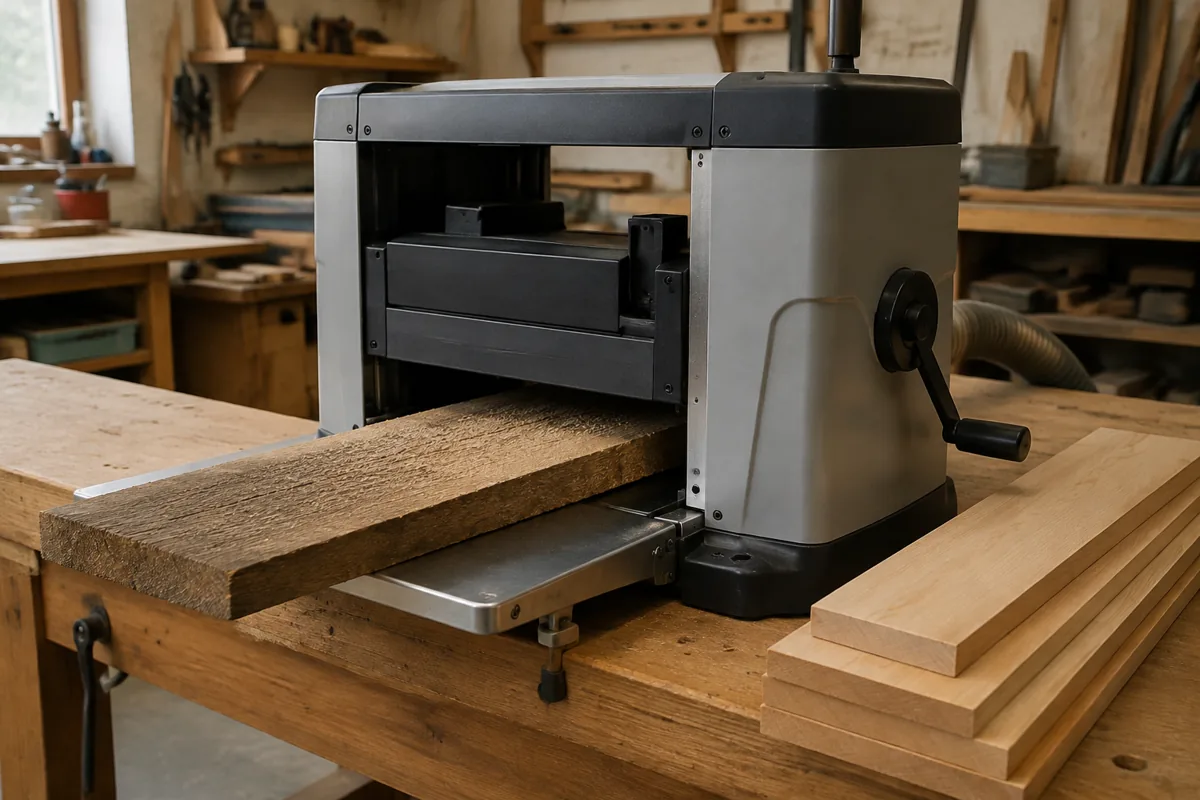
A planer can produce a board that is the same thickness from end to end yet still cut a slight taper from one side to the other. One cause is a cutterhead that is not parallel to the planer’s table or bed. Before adjusting anything, check the machine’s manual: some planers have a fixed cutterhead and an adjustable table, while others provide a different alignment procedure. The goal is to measure the gap at both ends using the same reference surface, then decide whether the difference is real and correctable.
Contents
What parallel alignment means
The cutterhead axis should be parallel to the planer bed across the width of the cut. If one end is closer to the bed, the knives or inserts remove more material on that side. A board may come out measurably thinner along one edge, or it may show uneven cutter marks. A planer’s feed rollers, table extensions, and bed rollers can also affect results, so a tapered board alone does not prove the cutterhead is out of alignment.
Check the alignment against the manufacturer’s stated tolerance if one is provided. There is no single tolerance that applies to every planer. For a small benchtop machine, a difference of a few thousandths of an inch may be difficult to distinguish from measurement error; a larger difference, such as 0.010 inch across the cutterhead, is worth investigating. Do not treat those figures as a substitute for your manual’s specification.
Tools and safety
Unplug the planer before opening covers, removing guards, or putting a gauge near the cutterhead. Keep hands clear of knife edges and inserts. If you need to rotate the cutterhead to reach measuring points, turn it only by the method described in the manual; never power the machine with a measuring tool in place.
A dial indicator on a stable base gives repeatable readings, but a precision straightedge and feeler gauges can be adequate for a basic check. A dial indicator with a magnetic base is useful if you also maintain a jointer or table saw. For occasional home-shop checks, a straightedge and feeler-gauge set costs less and may be all you need. A carpenter’s ruler or an unverified shop-made spacer is not precise enough to diagnose a small error confidently.
Choose a measuring method
| Method | Best for | Trade-off |
|---|---|---|
| Dial indicator | Comparing left and right readings with fine resolution | Needs a stable mount and careful setup |
| Straightedge and feeler gauges | A quick check with basic shop tools | More sensitive to straightedge quality and placement |
| Test board | Confirming how the planer cuts in practice | Shows the combined effect of alignment, rollers, and workpiece handling |
Set up the planer
Clean pitch, dust, and chips from the bed and the surfaces used as references. Check that the planer is level and stable, though a level machine is not automatically a parallel machine. Raise or lower the table to a convenient position and lock it if the design allows. Remove the dust hood only if the manual permits it and doing so is needed for access.
Inspect the cutterhead before measuring. Loose knives, unevenly seated inserts, packed resin, or damage can produce misleading readings and poor cuts. Do not measure from a knife edge if the machine’s procedure specifies a different reference point. On an insert head, use corresponding insert locations at each end; on a straight-knife head, follow the manual’s instructions for positioning the cutterhead and measuring across the knives.
Measure both ends
For a dial-indicator check, secure the base to a surface that will not shift and arrange the probe to contact the specified cutterhead reference point. Take a reading near the left end, then move the setup to the corresponding point near the right end without changing the table height. Repeat each reading to confirm it returns to the same value. If the indicator changes when you repeat a measurement, improve the mounting or clean the contact surfaces before drawing a conclusion.
With a straightedge and feeler gauges, place the straightedge on the bed in the position specified by the manual and compare the gap at each side of the cutterhead. Use light, consistent pressure; forcing the straightedge can flex it or rock it on a high spot. Record the largest feeler gauge that fits without force at each end. The difference between the two readings is the cross-width error. Check more than one position if the manual calls for it, and avoid comparing unlike surfaces.
It can help to note the readings in a small table or notebook: left, right, difference, tool used, and table position. That makes it easier to tell whether an adjustment actually improved alignment rather than merely changing the setup.
Confirm with a test cut
After the static check, run a straight, flat test board through the planer using a light cut, around 1/32 inch or less if the machine can take that consistently. Mark the board’s left and right edges before feeding it, and measure thickness at matching points with calipers or a reliable thickness gauge. Repeat with the board turned end for end. If the thin side stays on the same side of the machine, alignment or machine setup is more likely at fault. If the taper follows the board, the stock itself may be twisted or tapered.
A test cut is a confirmation, not a replacement for measurement. Feed rollers, snipe, a bowed board, and uneven pressure can all distort the result. Keep the board supported and feed it according to the manual; do not press down hard on one side to force a particular outcome.
If the readings are different
First repeat the measurement. Check for dust under the straightedge or indicator base, a loose table lock, a dull or mis-seated knife, and a reference surface that is not truly flat. Then consult the manual for the adjustment procedure. Depending on the planer, correction may involve table leveling screws, column adjustments, or a service procedure that should not be improvised. Make small changes, remeasure both ends, and tighten hardware to the specified torque if the manual gives one.
Do not shim a column or alter a cutterhead bearing position without an approved procedure. Incorrect changes can bind the mechanism, reduce cutting clearance, or create a new error. If the planer is under warranty, contact the manufacturer before disassembly. For a persistent error beyond the stated tolerance, a service technician may be the safer and cheaper choice than replacing parts by guesswork.