How to Correct a Jointer Table That Is Out of Parallel
What's inside
As an Amazon Associate I earn from qualifying purchases. This post may contain affiliate links at no extra cost to you.
Contents
Symptoms of Tables Out of Parallel
A jointer that is out of parallel will not cut flat, no matter how sharp the knives are or how carefully you feed. The classic symptom is a taper along the length of the board: you joint one face flat, flip it, and the board rocks or shows a gap in the middle. Another tell is snipe at the very end of the cut, or a board that is flat when checked with a short straightedge but shows twist when you check it diagonally. If you can take a light cut and get a surface that looks good, then take a second pass and remove material only at the front or back, the tables are not coplanar.
Before you adjust anything, rule out the cutterhead. Set the knives or inserts to the outfeed table first. The outfeed table must be exactly at top dead center of the cutterhead. If the knives are high or low by even 0.002-0.003″, you will chase table parallelism forever and never get a straight edge. Lock the outfeed table, bring a straightedge from the outfeed over the cutterhead, and rotate the head by hand. The knives should just kiss the straightedge and drag it forward about 1/8″ to 3/16″ without lifting it.
How to Diagnose Parallelism Correctly
You need two references: a reliable straightedge and a way to measure small gaps. A 48″ to 50″ precision straightedge is the minimum for a 6″ or 8″ jointer. A 24″ level or aluminum rule is not straight enough; most are out by 0.005″ or more.
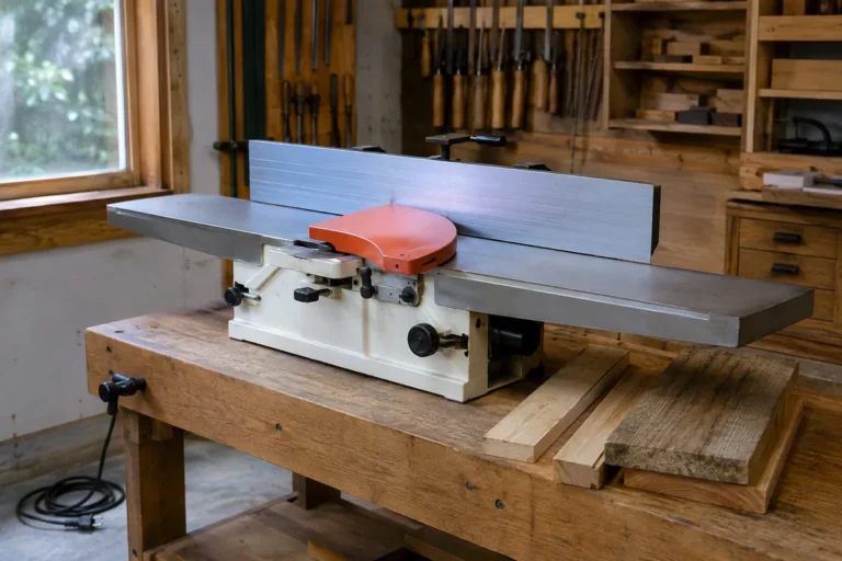
Start with the jointer unplugged and tables clean. Raise the infeed table until it is level with the outfeed table. Lay the straightedge lengthwise so it bridges both tables, sitting over the cutterhead. Use a feeler gauge set to check the gaps at four points: front and back near the cutterhead, and front and back at the far ends of the tables. Write the numbers down.
Then check diagonally and across the width. If both tables are flat themselves but show a consistent gap that gets larger toward one end, the tables are out of parallel end-to-end. If the gap is larger on the fence side vs. the front side, they are out side-to-side. Most jointers allow less than 0.002″ total deviation over the full length for good work. Anything over 0.004″ will show up as twist or taper in panels and glue-ups.
For a more precise reading, mount a dial indicator with magnetic base on the cutterhead or on a stable block on the outfeed table and sweep it along the infeed table. Zero it at the cutterhead end, then slide toward the end of the infeed. This tells you exactly how much the infeed drops or rises. Repeat on both front and back edges. This is faster and more repeatable than feeler gauges alone, especially on parallelogram jointers.
Know Your Jointer Type Before You Adjust
There are two common mechanisms, and they adjust differently. Forcing the wrong adjustment will score the ways or crack a casting.
| Feature | Dovetail Ways | Parallelogram |
|---|---|---|
| How to Identify | Two angled V-shaped ways, one or two long gib screws on the side, tables slide up/down at an angle | Four eccentric cams or eccentrics under each table, tables move straight up/down and stay more parallel |
| Parallelism Adjustment | Gib screws and gib strip tension; sometimes shimming the ways or scraping. No factory eccentric cams. | Rotating eccentric bushings/cams at each corner of the table to raise/lower that corner independently |
| Height Adjustment | Handwheel and lead screw moves table along dovetail | Handwheel moves parallelogram linkage; height and parallelism are separate controls |
| Common on | Most 6″ and older 8″ jointers, benchtop models | Modern 8″ and larger cabinet jointers, helical-head models |
| Difficulty | More trial and error; sensitive to gib tightness and wear | More precise but requires patience and a dial indicator |
If you are not sure which you have, crank the infeed table up and look underneath with a flashlight. Dovetail ways are obvious long angled slides. Parallelogram tables show four arms with cams and lock nuts.
Correcting a Dovetail-Ways Jointer
Dovetail jointers have no independent corner adjustment. Parallelism is controlled by the fit of the gibs and the cleanliness of the ways. Any grit, dried oil, or burr here magnifies error.
First, loosen the gib lock screws slightly, then clean the ways thoroughly with mineral spirits and a non-metallic brush. Inspect for nicks. A small burr can lift the table 0.003″ at one end. Stone it lightly if you find one. Apply a thin coat of dry paste wax or way oil, not thick grease.
To set the gibs, raise the infeed table to about 1/16″ below the outfeed. Snug the gib screws evenly until the table slides without play but without binding. The test: with the lock lever released, the table should move up and down through its full range with steady handwheel resistance and no lateral wiggle if you push the front edge side to side. If it is tight at the top and loose at the bottom, the gib is tapered or worn and you have two options: replace the gib strip, or lap it slightly on fine sandpaper on a flat surface.
Recheck parallelism after each gib adjustment. On these machines you are not bending the table; you are ensuring it travels true. If the table itself is worn low on one side after years of use, gib adjustment alone will not fix it. A machine shop can regrind the ways, but for a benchtop or light-duty 6″ jointer, that cost often exceeds the value of the machine. In that case a cheaper option is to live with a 0.002-0.003″ deviation and take lighter finish passes, or shim the gib with brass shim stock on the low side. Do not over-tighten gibs to force parallelism — it will wear the ways rapidly and make height adjustment sticky and inaccurate.
Correcting a Parallelogram Jointer
Parallelogram jointers are designed to be adjusted. Under each table there are four eccentric bushings, usually with a lock nut and a slotted head or hex. Turning the eccentric raises or lowers that corner by a few thousandths. The outfeed table should be set first and left alone as your reference, then the infeed is brought parallel to it.
Lock the outfeed table at cutterhead height. Bring the infeed table up until it is within 0.010″ of the outfeed. Set your dial indicator on the outfeed and zero it on the infeed near the cutterhead on the fence side. Sweep to the far end of the infeed on the same side. The reading is your end-to-end error on that side. Loosen the lock nuts for the two cams on that side and rotate them a tiny amount — 1/16 of a turn can be 0.002″. Re-tighten and re-measure. Then repeat on the front side.
Work in small steps and always recheck both sides. Adjusting the front cams will slightly affect the back reading and vice versa. Expect three to five iterations to get under 0.002″ over the full length. When you tighten the lock nuts, the reading often shifts 0.001″. Anticipate this and hold the eccentric with a screwdriver while you tighten.
Failure modes to avoid: do not force an eccentric past its stop, and do not loosen all four cams at once — the table can drop suddenly and chip the casting. Keep the table supported with the handwheel while you work. If a cam is frozen from rust, soak it with penetrating oil and work it back and forth instead of using excessive torque.
When Shimming Is Necessary
If your jointer has no eccentrics and the gibs are set correctly but you still have a side-to-side error of 0.004″ or more, the table or ways may be out from the factory or worn. A field fix is to shim between the table and the dovetail saddle, or under the outfeed table ways if the outfeed is the one that is low. Use 0.001″ or 0.002″ brass or stainless shim stock, never paper or aluminum foil which compresses.
Cut a strip to fit under the gib or on the low way, install, and recheck. This is tedious and should be considered a last resort. If you need more than 0.005″ of shim to get parallel, the machine has a deeper problem — a twisted base, bent table, or worn ways — and further shimming will cause binding. At that point, have the tables checked on a surface plate or consider replacement.
Final Verification and Cut Test
After mechanical adjustment, do a cut test. Joint two 30″ to 36″ long boards on face, about 4″ to 5″ wide, taking a 1/32″ cut. Put the jointed faces together and hold them up to light. No light should show through. Check for taper with calipers at both ends — difference should be under 0.003″. Then edge-joint one board and check it against a known square.
Recheck after a week of use. Cast iron moves slightly with temperature and vibration, and lock nuts can settle. If you had to adjust more than 0.006″ initially, run the tables up and down several times and re-measure before you call it done. Keep the ways waxed and keep pitch off the tables; buildup under a straightedge during measurement is a common false reading.
A jointer that holds 0.0015″ to 0.002″ parallelism will produce glue-ready edges without forcing the clamps to pull a bow flat. You do not need laboratory precision — you need repeatable, stable coplanarity across the full length of both tables, on both the fence and front sides.