How to Check Planer Table Parallelism to the Cutterhead
What's inside
As an Amazon Associate I earn from qualifying purchases. This post may contain affiliate links at no extra cost to you.
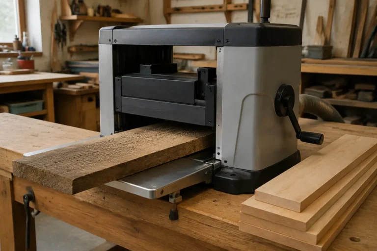
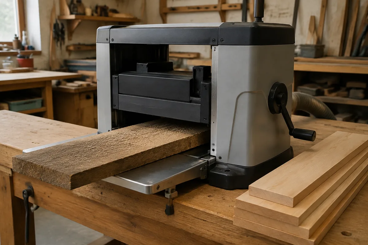
A planer table does not need to be perfectly parallel to the shop floor, but it does need to stay parallel to the cutterhead. If it is tilted, the machine may cut one side of a board more heavily, leave a tapered thickness, or produce snipe that adjustment alone cannot cure. The check is straightforward, provided you measure from the cutterhead or cutterhead housing rather than from the machine’s exterior.
Contents
What parallelism means
The cutterhead is the reference. The table should be the same distance from it at the left and right sides, and normally at the front and rear as well. On a planer with a fixed cutterhead and four synchronized lift screws, a square table can be slightly high or low relative to the cutterhead and still work correctly. A table that changes angle across its width cannot.
Before measuring, unplug the planer and remove the dust hood. Take out the knives or cutter inserts if the design makes this safe and practical. If you leave them installed, rotate the cutterhead so a knife edge is not directly above your measuring tool. Lock the table height mechanism and clean sawdust from the table, lift screws, and cutterhead area.
Tools you can use
A dial indicator is the most repeatable option. A planer-specific dial indicator and magnetic base can measure the actual gap while you slide it across the table. A height gauge, test indicator, or a straight bar with feeler gauges also works.
| Tool | Useful accuracy | Best use | Limitation |
|---|---|---|---|
| Dial indicator | 0.001 inch or 0.01 mm resolution | Comparing multiple points quickly | Needs a rigid mounting method |
| Precision straightedge and feeler gauges | About 0.002 inch with care | Low-cost workshop checks | Harder to reference the cutterhead directly |
| Steel rule or framing square | Rough check only | Finding obvious tilt or damage | Too flexible and inaccurate for final adjustment |
| Planer alignment jig | Depends on its construction | Checking portable planers without a base | Must be square and rigid first |
The cheaper option is fine if you only need to find a large error. A straightedge and feeler gauges can identify a 0.010-inch difference. If you are chasing a few thousandths, use a dial indicator and a rigid bar or fixture. Do not trust a cheap magnetic base if its arm flexes when you touch it.
Dial-indicator method
Make a rigid bridge that spans the cutterhead opening, or use a commercial planer table alignment jig designed for your machine. The bridge must sit on the table without rocking. Mount the indicator so its tip contacts the cutterhead at a consistent reference point, or contacts a straight reference bar secured to the cutterhead.
With the table close to the cutterhead, zero the indicator at the left side. Move the indicator to the right side without changing the table height. Record the difference. Repeat at the front and rear of the table. Then rotate the cutterhead by hand and repeat the reading at several positions. A cutterhead may have slight runout, and one knife or insert can sit higher than another.
For a practical woodworking planer, a left-to-right difference of 0.001 to 0.003 inch is very good. Around 0.005 inch is usually usable, particularly on a portable machine. At 0.010 inch, expect tapered boards or unequal cutting. These are working guidelines, not universal factory specifications; check the manual when one is available.
Measure at both ends of the table if the table is long or has separate extension sections. If the front and rear readings disagree, the table may be twisted, a lift screw may be out of synchronization, or the table casting may not be flat. If only one corner is high, inspect for packed chips, a damaged mounting point, or a bent lift screw before turning any adjustment nuts.
Straightedge and feeler-gauge method
Place a known-straight bar across the table, parallel with the cutterhead. A ground steel straightedge is preferable; a construction level is not automatically straight enough. Raise the table until the bar is close to the cutterhead, then check the gap between the bar and the cutterhead reference with feeler gauges at both sides.
Another method is to place the straightedge on the table and use a depth gauge or feeler gauges to compare its distance to the cutterhead at several points. Keep the straightedge in the same position while comparing left and right. Do not measure to the knife edge unless you can rotate the cutterhead and confirm that the knife is seated consistently.
Take at least three readings on each side. If the result changes when you reverse the straightedge, the straightedge may be bowed or the table may have dirt underneath it. Clean, repeat, and mark the high and low corners before adjusting anything.
Adjusting a four-post planer
Most four-post planers use a chain or belt to synchronize the lift screws. Make only small changes. Unplug the machine, loosen the appropriate lift-screw sprocket or coupling, and move the screw needed to bring the table into alignment. The exact procedure varies widely, so use the service instructions if possible.
Do not simply turn one exposed screw while the chain remains tight. That can preload the chain, move the other screws when the table is raised, or leave the lift system out of phase. After each adjustment, raise and lower the table through its working range, lock it, and measure again. A table that is parallel at one height but not another points to a synchronization problem, bent screw, worn nut, or damaged chain.
Portable planers with a single central lift mechanism may not offer a true parallelism adjustment. First verify that the planer is sitting on a flat, stable base. Check that the side columns are tight and that the table is not flexing under pressure. If the error remains, replacement parts or a manufacturer-approved alignment procedure may be the only sensible solution.
Avoid false diagnoses
Snipe at the board’s ends is often caused by lifting or lowering the workpiece as it enters and exits, not by a nonparallel table. Feed rollers that are dirty, weak, or incorrectly adjusted can also cause uneven cuts. Check table rollers, cutterhead knife height, pressure-bar settings, and dust buildup before dismantling the lift system.
Test with a board at least 24 inches long and make light cuts of about 1/32 inch. Mark the top face and measure thickness at both ends and along both edges. If the machine cuts a consistent taper across the board, parallelism is a strong suspect. If the result varies from pass to pass, look first at feeding technique, board movement, and cutterhead or roller condition.
Once the readings are within a sensible tolerance, lock the adjustment hardware, reinstall the guards and dust hood, and make a test cut. Accuracy matters, but a rigid, clean, safely adjusted planer matters more than chasing a reading that the machine cannot hold under load.